
Updated on 06/07/2015 : Thank you @WaterContext for pointing an error in the Wire Colour to GPIO Pin table.
In this tutorial, we will wire up and write the code required to create a universal application that will, turn an LED on and off each time the button is pressed. It is important to understand both the hardware and software.
What is GPIO
GPIO stands for:
- General
- Purpose
- Input
- Output
GPIO pins can either set or reads a voltage, this allows the controller (in this case the raspberry pi) to communicate with a wide range of hardware electronics using code. Each of the GPIO pins has a pre-defined use that can be read the following link.
You’ll need
To complete the tutorial, outline in this post, you will need the following components
- A raspberry pi 2 running Windows 10 IoT
- A button
- An LED
- A 330 Ω resistor
- A 10k Ω resistor
- A breadboard
- Several connector wires
Wiring it all up
Following the diagram below:
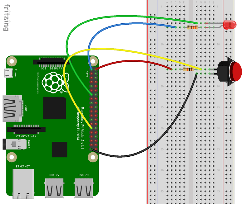
| Wire Colour | Pi GPIO (Pin#) |
|---|---|
| Red | 5V (02) |
| Black | Ground (39) |
| Blue | 3V3 (01) |
| Green | GPIO27 (13) |
| Yellow | GPIO05 (29) |
Explaining the Circuit
To explain the Circuit above we will break it into two questions:
Why doesn’t the LED turn on even though it’s directly connected to the V3.3?
For an LED to light up, there must be a flow of current and sufficient voltage. An LED is a type of diode that only allows current to flow in one direction, from the positive terminal (longer leg) to negative terminal (flatter side). Ideally there is no voltage drop over a diode. However, the run of the mill LED needs to consume 0.7V to light up and allow the current to continue flow through.
But on one side we have GPIO27 that we initialized to high (3.3v) on the other side we have the 3v3 pin (3.3v). If the current flows from 3v3 pin through the resistor and diode, it will be less than 2.6v when it reaches GPIO27. (3.3-0.7-Resistor Voltage Drop) However, the voltage at GPIO27 is 3.3v. The problem that occurs is that there are two possible values for the voltage at this point depending on which path the current flows. This causes a broken circuit. In an open or broken circuit, there is still voltage at the pins but no current can follow through the rest of the circuit. Since there is no current flowing through the circuit and in turn no power, the LED can not light up.
We can solve this issue by setting the output of the GPIO27 pin to low (0V). This effectively resolves the broken circuit since the negative terminal of the LED is now less than the required 2.6v. The resistor will drop the remaining 2.6v so that the voltage at GPIO27 will remain as 0v and current will flow through the circuit. A demonstration of the flow can be seen below:
What does the button do?
The GPIO05 pin was initialized as an input and observes the voltage at the point it’s connected to the circuit like a multimeter. The effect it has on the circuit is negligible and can, therefore, be ignored.
The circuit has the 5v pin attached to a resistor and connected to a button that is connected to ground. While the button is open, the circuit is broken. Once again no current can flow. However, the voltage at the pin remains. If no current is passing through the resistor, it will not affect the voltage as per ohm’s law. This means the voltage at this side of the button is read as 5v by GPIO05.
When the button is pressed, the circuit completes. The current follows through the resistor to ground. The voltage will drop over the resistor by 5v as the ground has a voltage of 0v.The GPIO05 would read the “pull down” from 5v to 0v.
Writing the code
In this tutorial, the Windows 10 universal application I create will be called GPIOIntroPi.
1.Add the required references
A reference to the Windows IoT Extension SDK is required.

2.Update mainpage.xaml
First let’s create the UI for this universal application.
3.Initialize the GPIO on the Pi
In this step we will create a method to initialise the GPIO pins.
As can be seen in the code above we use GpioController.GetDefault() to get the GPIO controller.
Is this function, returning null? Then the device you’re attempting to use doesn’t have a GPIO controller!
Now that we have initialised the GpioController, we can now set up our pins ready for use
In the code above we perform the following steps:
- We open the pin by calling GpioController.OpenPin() with the PB_PIN and LED_PIN value.
- Set the pins to the correct mode using the GpioPin.SetDriveMode() function
- Set all pins to off (which is high in this post) with GpioPin.Write()
4. Use the button to control the LED
Due to how we connect the LED to the 3.3 Volts power supply. We need to set the pin to low to have the LED light up. Therefore, we will use the GpioPin.Write to toggle between high and low, when the button is pressed.
Special thanks to my younger brother Anthony, for helping me to understand the hardware aspect of this blog post.
Feel free to tweet me comments, feedback or questions to @ChrisBriggsy.